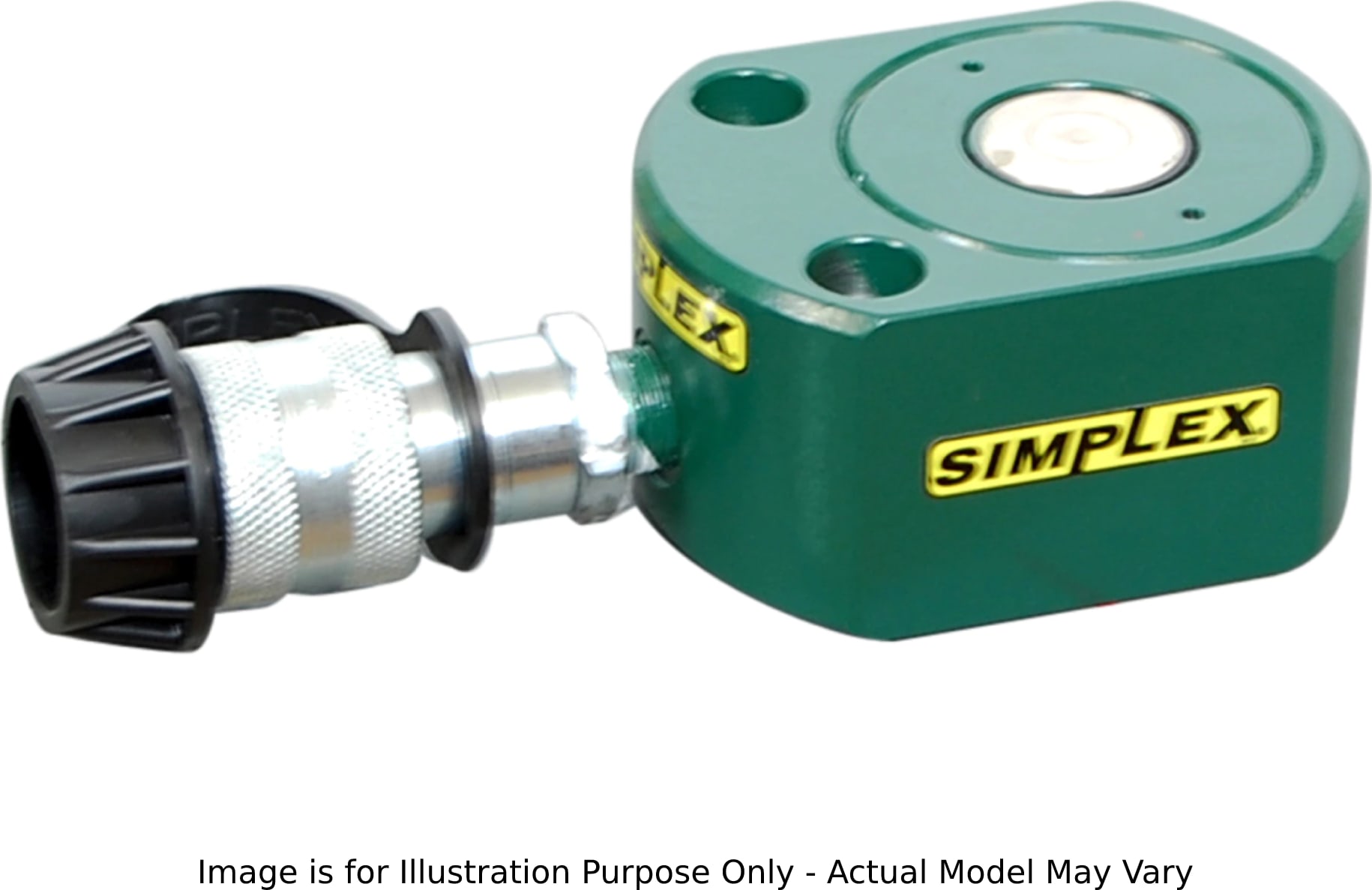
Enerpac RFS30 — низкопрофильный гидравлический цилиндр, грузоподъемность 30 тонн, ход поршня 0,5 Вт
21.01.2025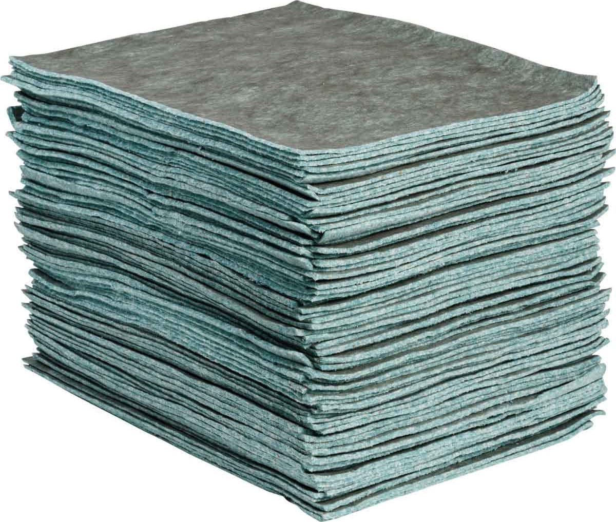
Brady RFP500 – впитывающая прокладка Re-Form Plus
21.01.2025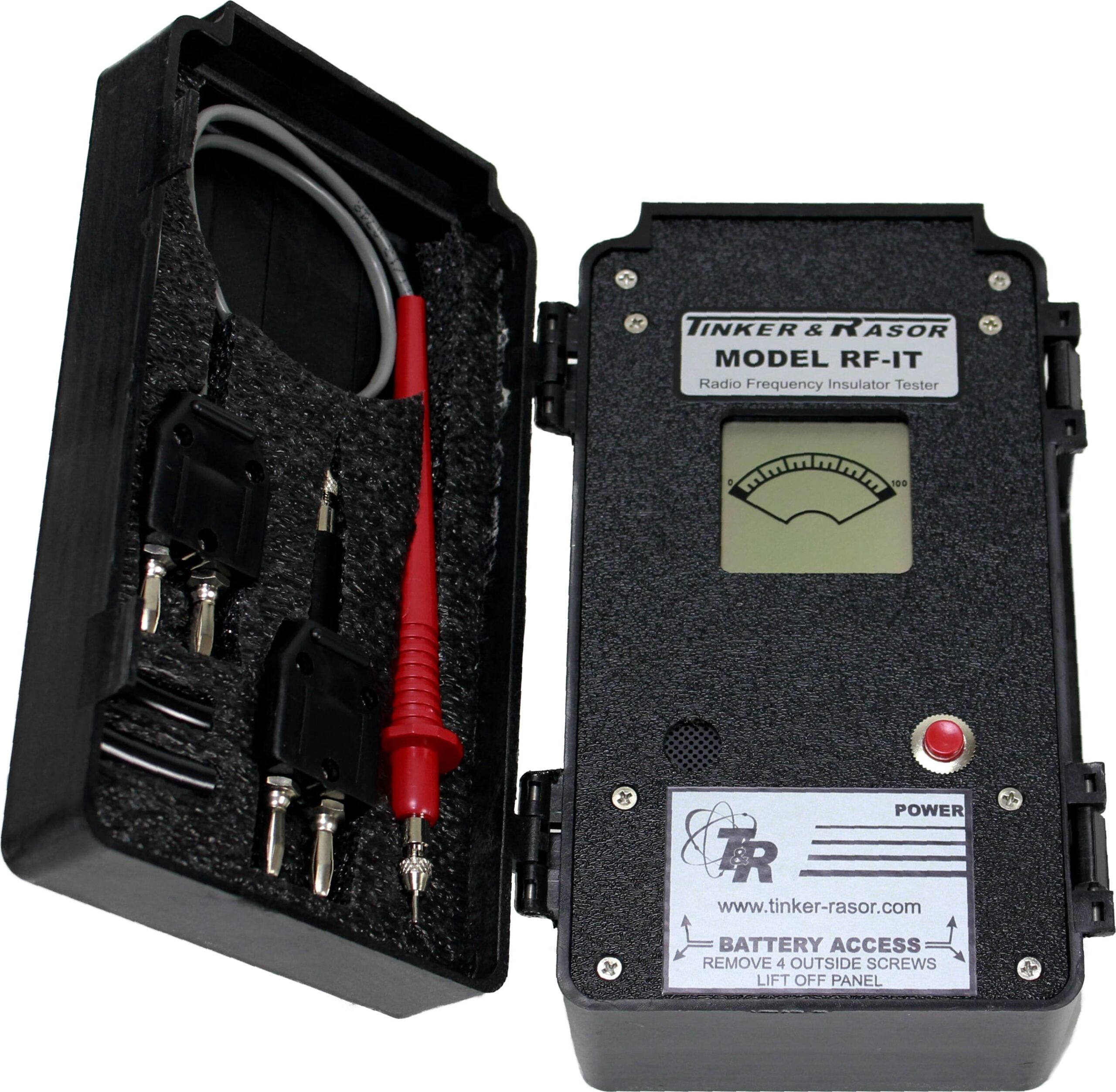
Tinker & Rasor RF-IT – Above Ground Insulator Tester
Insulator Tester, Above Ground Radio Frequency
151875,00 ₽
Description Tinker & Rasor RF-IT – Above Ground Insulator Tester
- Radio Frequency used to test effectiveness of above ground pipeline insulators
- Can be used on structures with or without cathodic protection
- Locates shorted bolts – pinpoints precise contact point
- Handheld instrument – 8in x 4in x 3in, 2lbs
- Housed in a tough polypropylene case
The Model RF-IT is a highly sensitive device used to test above ground pipeline insulators. The Model RF/IT Insulator Tester is effective in the testing of pipeline insulators in parallel or series installations, even if one or more of the insulators are not operating properly. The tests conducted are fast and accurate.
This unit can also be used for flange bolts shorts. The automatic RF-IT allows the operator to pinpoint the precise contact point. The RF-IT emits an audible beep, and when the operator gets closer to the point of contact, the unit starts beeping faster. At the same time, the sliding scale LCD meter moves from right to left.
Testing methods
Two common methods used to measure a pipeline insulator are DC resistance and Radio Frequency Skin Effect. Radio Frequency Skin Effect is the phenomenon where the apparent resistance of a conductor increases as the frequency increases. With DC, the charge carriers have an even distribution throughout the area of the conductor. However, as the frequency increases, the charge carriers subsequently move towards the edge of the wire, decreasing the effective area and increasing the apparent resistance.
Because the Radio Frequency meter does not use a DC voltage, it is unaffected by DC or AC voltages under 50 volts and there is no need to disconnect the cathodic protection voltage applied to the pipe and/or structure. Another advantage of the skin effect is that errors due to diameter, relative permeability of the pipe and insulator distance are negligible.
To measure an insulator using the Radio Frequency method is similar to that of the DC measurement. The probes are placed across the insulator and the technician reads the display. Maximum deflection of the meter (100 or all the way to the Right) indicates a resistance of a high enough value as to indicate a good insulator, whereas if the insulator is shorted or has a low electrical resistance, the meter will only show reads to the left of top center (older analog meter shows one or two bars from the Left).
Test above ground pipeline insulators to pinpoint the precise contact point.
The RF-IT emits an audible beep. When the operator gets closer to the point of contact the unit starts beeping faster. At the same time, the LCD meter moves from left to right.
Похожие товары
-
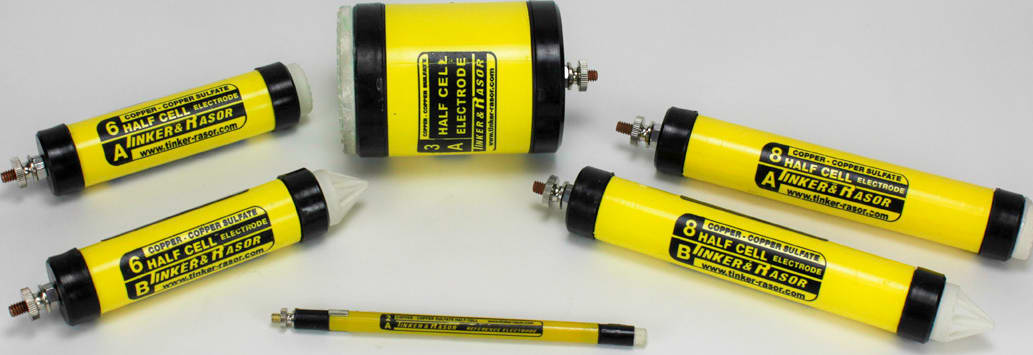
Tinker & Rasor 8A – электрод сравнения из меди и сульфата меди (1-1/4” x 8”, плоский наконечник)
13500,00 ₽1-1/4′ x 8′ Copper-Copper Sulfate Half Cell Electrode (Flat tip)
-
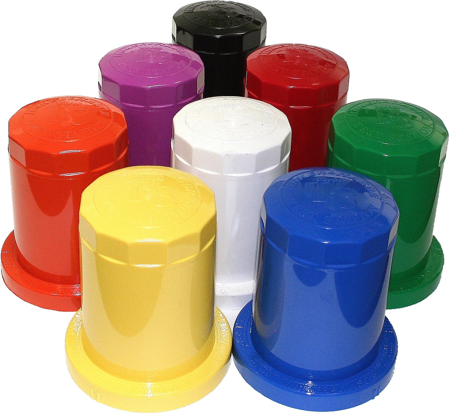
Tinker & Rasor T-3 — испытательная станция с крепежом, 11 отверстий с 5 клеммами (укажите цвет при заказе)
6525,00 ₽Испытательные станции T-3 с полным комплектом оборудования