FLIR T131178 – Стрелки направления станции досмотра
19.01.2025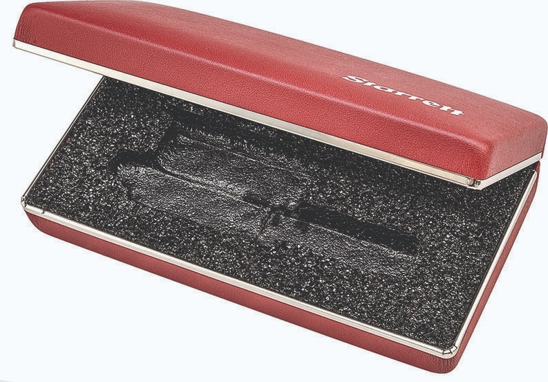
Starrett 940 – Стальной/виниловый футляр для микрометрических нутромеров 700, 700M
19.01.2025
Pico 9402-16 CDR – 16GHz, 2 Channel 9400 Series SXRTO with Clock and Data Recovery
Scope 9402-16 with clock recovery
5036625,00 ₽
Description Pico 9402-16 CDR – 16GHz, 2 Channel 9400 Series SXRTO with Clock and Data Recovery
- 16 GHz bandwidth, 22 ps transition time, 2 channels, clock and data recovery
- 2.5 TS/s (0.4 ps resolution) random equivalent-time sampling
- 12-bit 500 MS/s ADCs, ±800 mV full-scale input range into 50 Ω
- Pulse, eye and mask testing down to 45 ps and up to 11 Gb/s
- 10 mV/div to 0.25 V/div digital gain ranges
The PicoScope 9400 Series sampler-extended real-time oscilloscopes (SXRTOs) have two or four high-bandwidth 50 Ω input channels with market-leading ADC, timing, and display resolutions for accurately measuring and visualizing high-speed analog and data signals. They are ideal for capturing pulse and step transitions down to 22 ps, impulse down to 100 ps, and clocks and data eyes to 8 Gb/s (with optional clock recovery). The PicoScope SXRTOs offer random sampling, which can readily analyze high-bandwidth applications that involve repetitive signals or clock-related streams. The SXRTO is fast: random sampling, persistence displays and statistics all build quickly. The PicoScope 9400 Series has a built-in internal trigger on every channel, with pre-trigger random sampling to well above the Nyquist (real-time) sampling rate. Bandwidth is up to 16 GHz behind a 50 Ω SMA(f) input, and three acquisition modes-real-time, random and roll-all capture at 12-bit resolution into a shared memory of up to 250 kS.
The PicoSample 4 software is derived from the existing PicoSample 3 sampling oscilloscope software, which embodies over ten years of development, customer feedback and optimization.
The display can be resized to fit any window and fully utilize available display resolution, 4K and even larger or across multiple monitors. Four independent zoom channels can show you different views of your data down to a resolution of 0.4 ps. Most of the controls and status panels can be shown or hidden according to your application, allowing you to make optimal use of the display area.
A 2.5 GHz direct trigger can be driven from any input channel, and a built-in divider can extend the off-channel trigger bandwidth to 5 GHz. On the 16 GHz models, a further external prescaled trigger input allows stable trigger from signals of up to 16 GHz bandwidth and, from the internal triggers, recovered clock trigger is available (if optional clock recovery is fitted) at up to 8 Gb/s. With this option, recovered clock and data are both available on SMA outputs on the rear panel.
These compact units are small enough to place on your workbench close to the device under test. Now, instead of using remote probe heads attached to a large benchtop unit, all you need is a short, low-loss coaxial cable. Everything else you need is built into the oscilloscope, with no expensive hardware or software add-ons to worry about, and Pico does not charge for new software features and updates.
Typical applications
- Telecom and radar test, service, and manufacturing
- Optical fiber, transceiver, and laser testing (optical to electrical conversion not included)
- RF, microwave, and gigabit digital system measurements
- Signal, eye, pulse, and impulse characterization
- Precision timing and phase analysis
- Digital system design and characterization
- Eye diagram, mask and limits test up to 8 Gb/s
- Clock and data recovery at up to 8 Gb/s
- Ethernet, HDMI 1, PCI, SATA and USB 2.0
- Semiconductor characterization
- Signal, data and pulse/impulse integrity and pre-compliance testing
High-bandwidth probes
The PicoConnect 900 Series low-impedance, high-bandwidth probes are ideal companions for the PicoScope 9400 Series, allowing cost-effective fingertip browsing of fast signals. Two series are available:
- RF, microwave, and pulse probes for broadband signals up to 5 GHz (10 Gb/s)
- Gigabit probes for data streams such as USB 2, HDMI 1, Ethernet, PCIe and SATA
Bandwidth limit filters
A selectable analog bandwidth limiter (100 or 450 MHz, model-dependent) on each input channel can be used to reject high frequencies and associated noise. The narrow setting can be used as an anti-alias filter in real-time sampling modes.
Frequency counter
A built-in fast and accurate frequency counter shows signal frequency (or period) at all times, regardless of measurement and timebase settings and with a resolution of 1 ppm.
Clock and data recovery
Clock and data recovery (CDR) is now available as a factory-fit optional trigger feature on all models.
Associated with high-speed serial data applications, clock and data recovery will already be familiar to PicoScope 9300 users. While low-speed serial data can often be accompanied by its clock as a separate signal, at high speed this approach would accumulate timing skew and jitter between the clock and the data that could prevent accurate data decode. Thus, high-speed data receivers will generate a new clock, and using a phase-locked loop technique they will lock and align that new clock to the incoming data stream. This is the recovered clock, and it can be used to decode and therefore recover data accurately. Pico has also saved the cost of an entire clock signal path by now needing only the serial data signal.
In many applications requiring Pico oscilloscopes to view the data, the data generator and its clock will be close at hand and can trigger off that clock. However, if only the data is available (at the far end of an optical fiber for instance), the CDR option is needed to recover the clock and then trigger off that instead. The CDR option may also be needed in demanding eye and jitter measurements. This is because Pico wants their instrument to measure as exactly as possible the signal quality that a recovered clock and data receiver will see.
When fitted, the PicoScope 9400 CDR option can be selected as the trigger source from any input channel. Additionally, for use by other instruments or by downstream system elements, two SMA(f) outputs present recovered clock and recovered data on the rear panel.
SXRTO explained The basic real-time oscilloscope
Real-time oscilloscopes (RTOs) are designed with a high enough sampling rate to capture a transient, non-repetitive signal with the instrument’s specified analog bandwidth. This will reveal a minimum width impulse, but is far from satisfactory in revealing its shape, let alone measurements and characterization. Typical high-bandwidth RTOs exceed this sampling rate by perhaps a factor of two, achieving up to four samples per cycle, or three samples in a minimum-width impulse.
Random sampling
For signals close to or above the RTO’s Nyquist limit, many RTOs can switch to a mode called random sampling. In this mode the scope collects as many samples as it can for each of many trigger events, each trigger contributing more and more samples and detail in a reconstructed waveform. Critical to alignment of these samples is a separate and precise measurement of time between each trigger and the next occurring sample clock.
After a large number of trigger events the scope has enough samples to display the waveform with the desired time resolution. This is called the effective sampling resolution (the inverse of the effective sampling rate), which is many times higher than is possible in real-time mode.
This technique relies on a random relationship between trigger events and the sampling clock and can only be used for repetitive signals – those with relatively stable waveshape around the trigger event.
So is the SXRTO a sampling scope?
All this talk of sampling rates and sampling modes may suggest that the SXRTO is a type of sampling scope, but this is not the case. The name sampling scope, by convention, refers to a different kind of instrument. A sampling scope uses a programmable delay generator to take samples at regular intervals after each trigger event. The technique is called sequential equivalent-time sampling and is the principle behind the PicoScope 9300 Series sampling scopes. These scopes can achieve very high effective sampling rates but have two main drawbacks: they cannot capture data before the trigger event, and they require a separate trigger signal – either from an external source or from a built-in clock-recovery module.
Here’s a table to show the differences between the types of scopes mentioned on this page. The example products are all compact, 4-channel, USB PicoScopes.
Real-time scope SXRTO Sampling scope Model PicoScope 6407 PicoScope 9404-05 Series PicoScope 9404-16 Series PicoScope 9341-25 Analog bandwidth 1 GHz 5 GHz 16 GHz 25 GHz Real-time sampling? 5 GS/s 500 MS/s 1 MS/s Sequential equivalent-time sampling? No No 15 TS/s Random equivalent-time sampling? 200 GS/s 1 TS/s 2.5 TS/s 250 MS/s Trigger on input channel? Yes Yes Yes, but only to 100 MHz bandwidth – requires external trigger or internal clock recovery option. Pretrigger capture? Yes Yes No Vertical resolution? 8 bits 12 bits 16 bits Pico 9402-16 Inputs, Outputs, and Indicators
Power LED: Green under normal operation
Status/trigger LED: Indicates connection progress and trigger
Channel inputs: CH1 and CH2. You can enable either or both channels without affecting the sampling rate, only the capture memory (250 kS) is shared between the enabled channels
PRESCALE: 16 GHz external prescaled trigger (16 GHz model only)
RST: reset button
USB: The USB 2.0 port is used to connect the oscilloscope to the PC
CLK & DATA: Recovered clock and data from the currently selected trigger source and the built-in clock recovery module
12 V DC: Power input. Use only the earthed mains adaptor supplied with the oscilloscope
Похожие товары
-
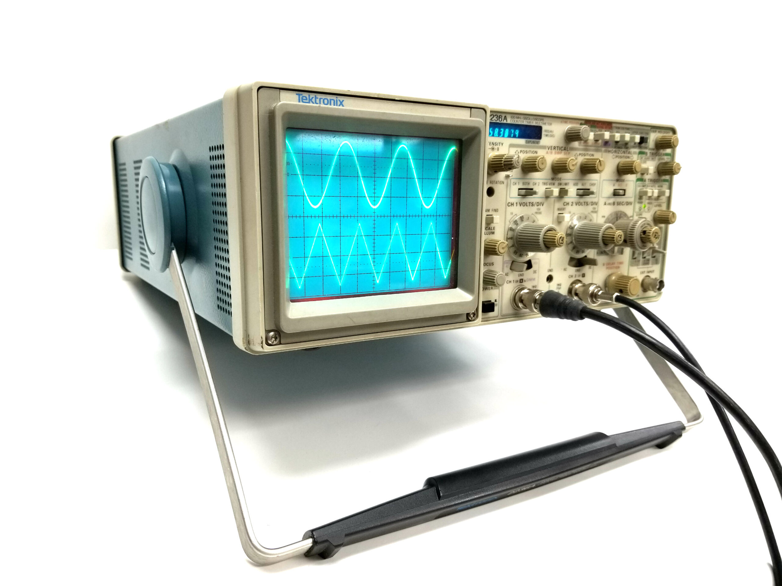
Tektronix 2236A 2 Channel 100Mhz Oscilloscope with DVM Frequency counter PARTS/REPAIR
28125,00 ₽Tektronix 2236A 2-канальный 100 МГц осциллограф с DVM-частотомером. УСТРОЙСТВО ДЛЯ РЕМОНТА ДЕТАЛЕЙ. Управление положением времени задержки B сломано – ручка присутствует. Функция DVM и частотомера. Нет руководства, измерительных проводов или лицевой крышки. Не нашли то, что искали? Используйте оранжевое поле поиска в правом верхнем углу этой страницы, чтобы настроить поиск. ***MPN 2236A ***OEM Tektronix, Inc (TEK) ***SKU*** 61148
-
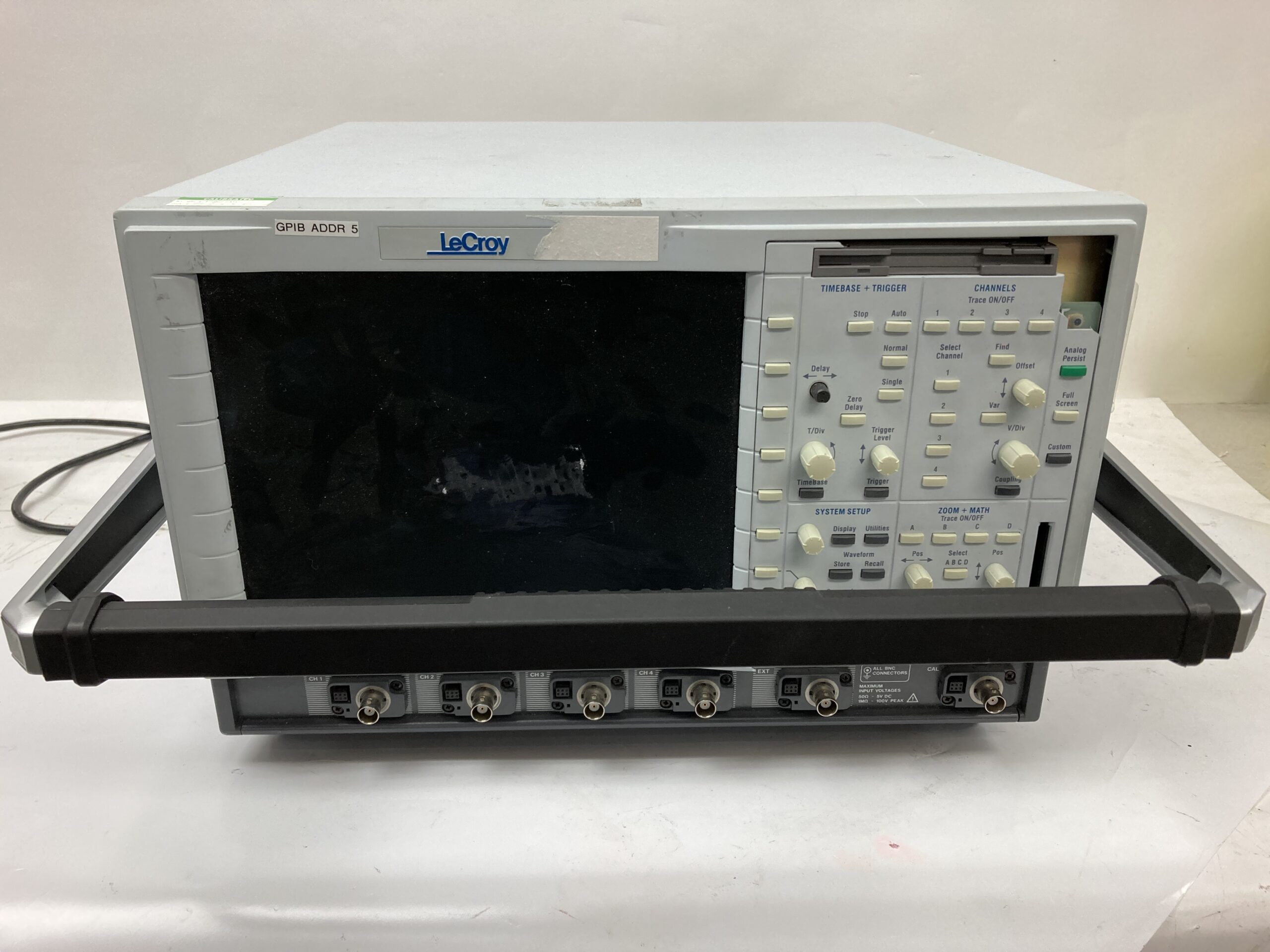
LeCroy LC684DM Oscilloscope (parts only)
224098875,00 ₽LeCroy LC684DM Oscilloscope (parts only) Needs Repair, Parts Only Check BMI Stock for More Items ***72120***
-
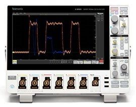
MSO44 4-BW-1000 Tektronix Mixed Signal Oscilloscope
3745000,00 ₽The MSO44 4-BW-1000 is a 1 GHz, 4 Channel, 6.25 GS/s, 31.25 MPts mixed signal oscilloscope from Tektronix.