Yokogawa 93033 Accessories
19.01.2025
FLIR T1010-28 – HD Thermal Imager w/ 28 Degree Lens
19.01.2025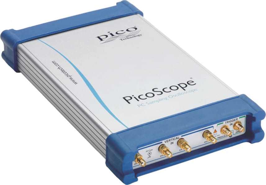
Pico 9302 PicoScope 20 GHz Sampling Scope Clock Recovery Kit
Sampling Oscilloscope 2 channels, 20 GHz, CDR
0,00 ₽
Description .va-img{box-shadow:1px 2px 3px #888,border-radius:5px,} .da-ilf-gsep{background: linear-gradient(rgb(7, 94, 133), rgb(38, 129, 169)), align:center} .da-ilf-gsep h3{ color: #ffffff, !important, } .da-1-4 { width: 23%, } .da-img { max-width: 100%, height: auto, margin: auto, } .da-ProdBody{ padding: 2%, margin: 0 auto, } .cr-list { list-style-image: url(/assets/1/7/850c3d3a3b4b40e68a2a2327508d61531.png), } .da-sm-img{ box-shadow: 1px 2px 3px #eeeeee, border-radius: 5px, } .da-sm-img:hover{ box-shadow: 1px 1px 2px 1px #aaa, transition: all 0.5s ease-in-out, } .da-overlay { position: fixed, top: 0, bottom: 0, left: 0, right: 0, background: rgba(0, 0, 0, 0.7), transition: opacity 50ms, visibility: hidden, opacity: 0, z-index: 1000, } .da-overlay:target { visibility: visible, opacity: 1, } .da-popup-img { margin: 70px auto, padding: 16px, background: #fff, border-radius: 5px, width: 50%, position: relative, transition: all 0.5s ease-in-out, max-width: 800px, } .da-popup-img h2 { margin-top: 0, color: #333, font-size:14px, } .da-popup-img .da-close { position: absolute, top: 0px, right: 10px, transition: none, font-size: 30px, font-weight: bold, text-decoration: none, color: #333, } .da-popup-img .da-close:hover { color: #888888, } .da-popup-img .da-content { max-height: 30%, overflow: auto, } .cr-stdwrp li {height: 38px, background: url(‘https://assets.tequipment.net/assets/1/7/RedCheckMark.png’) no-repeat left top, background-size: 36px 36px, padding: 3px 0px 3px 40px, /* reset styles (optional): */ list-style: none, font-size: 20px, } Pico 9302 PicoScope 20 GHz Sampling Scope Clock Recovery Kit
- Industry’s fastest sampling rate
- NRZ and RZ eye plots and measurements
- Serial data mask library and local editing
- Histogramming and statistical measurements
- Mathematics, FFT and custom formulas
- Intuitive Microsoft Windows user interface
The PicoScope 9300 Series
PicoScope 9300 Series USB Sampling Oscilloscopes
At 20 GHz bandwidth the PicoScope 9300 sampling oscilloscopes address digital and telecommunications applications of 10 Gb/s and higher, microwave applications up to 20 GHz and timing applications with a resolution down to 64 fs. Optional 11.3 Gb/s clock recovery, optical to electrical converter or differential, de-skewable Time Domain Reflectometry sources (40 ps/200 mV or 60 ps/6 V) complete a powerful, small-footprint and cost-effective measurement package.
9301 9302 9311 9312 9321 9341 20 GHz sampling oscilloscope ✔ ✔ ✔ ✔ ✔ ✔ 2 channels ✔ ✔ ✔ ✔ ✔ 4 channels ✔ Clock recovery (11.3 Gb/s) ✔ ✔ Optical input (9.5 GHz) ✔ TDR/TDT (40 ps / 200 mV) ✔ TDR/TDT (60 ps / 2.5 to 6 V) ✔ 20 GHz bandwidth in a compact USB instrument
PicoScope 9300 Series sampling oscilloscopes use triggered sequential sampling to capture high-bandwidth repetitive or clock-derived signals without the expense or jitter of a very high-speed clocked sampling system such as a real-time oscilloscope. 20 GHz bandwidth allows measurement of 17.5 ps transitions, and low sampling jitter enables timing resolution down to 0.064 ps. Sequential sampling rate of 1 MS/s, unsurpassed by other sampling oscilloscopes, enables rapid building of waveforms, eye diagrams and histograms.
These two and four channel units occupy very little space on a workbench and are small enough to carry with a laptop for on-site testing. Furthermore, instead of using remote probe heads attached to a large bench-top unit, you can position the 9300 scope right next to the device under test and connect to it with short, low-loss coaxial cables.
Everything needed to make high-performance waveform measurements is built into the oscilloscope, with no optional and expensive hardware or software add-ons to worry about.
Triggers and clock data recovery (CDR) 14 GHz prescaled trigger
The PicoScope 9300 scopes have a built–in high–frequency trigger with frequency divider. Its trigger bandwidth of up to 14 GHz allows measurements of microwave components with extremely fast data rates.
100 MHz internal direct trigger
The 9300 scopes are equipped with a built–in internal direct trigger from each channel for signals up to 100 MHz. This full-function trigger also provides level, slope, hysteresis and holdoff controls.
Built–in 11.3 Gb/s clock data recovery (CDR)
To support serial data applications in which the data clock is not available as a trigger, the PicoScope 9302 and 9321 models include a clock recovery trigger to regenerate the data clock from the incoming serial data. A divider accessory kit is included to route the signal to both the clock recovery and oscilloscope inputs.
Pattern sync trigger and eye line mode All models in the PicoScope 9300 series can internally generate a pattern sync trigger derived from bit rate, pattern length, and trigger divide ratio. This enables them to build up an eye pattern from any specified bit or group of bits in a sequence.
Eye line mode works with the pattern sync trigger to isolate any one of the 8 posssible paths, called eye lines, that the signal can make through the eye diagram. This allows the instrument to display and isolate effects such as data-dependent jitter, offset and overshoot for each trajectory. TDR / TDT analysis
The PicoScope 9311 and 9312 models include a built-in differential step generator for time domain reflectometry and time domain transmission measurements. This feature can be used to characterize transmission lines, printed circuit traces, connectors and cables with as little as 1.5 cm resolution.
The PicoScope 9312 is supplied with external tunnel diode pulse heads that generate positive and negative 200 mV pulses with 40 ps system rise time. The PicoScope 9311 generates large-amplitude differential pulses with 60 ps system rise time directly from its front panel and is suited to TDR/TDT applications where the reflected or transmitted signal is small.
The PicoScope 9300 Series TDR/TDT models include source deskew with 1 ps resolution and comprehensive calibration, reference plane and measurement functions. Voltage, impedance or reflection coefficient (ρ) can be plotted against time or distance.
The PicoScope 9311 and 9312 are supplied with a comprehensive set of calibrated accessories to support your TDR/TDT measurements. These include cables, signal dividers, adaptors, attenuator and reference load and short.
Optional 9.5 GHz Optical Input
The PicoScope 9321 includes a built-in, precision optical-to-electrical converter. With the converter output routed to one of the scope inputs (optionally through an SMA pulse shaping filter), the PicoScope 9321 can analyze standard optical communications signals such as OC48/STM16, 4.250 Gb/s Fibre Channel and 2xGB Ethernet. The scope can perform eye pattern measurements with automatic measurement of optical parameters including extinction ratio, S/N ratio, eye height and eye width. With its integrated clock recovery module, the scope is usable to 11.3 Gb/s. The converter input accepts both single-mode (SM) and multimode (MM) fibers and has a wavelength range of 750 to 1650 nm.
SMA Bessel-Thomson pulse-shaping filters
A range of Bessel-Thomson filters is available for standard frequencies. These filters are essential for accurate characterization of signals emerging from an optical transmission system. The first eye pattern, above left, shows the ringing typical of an unequalized O/E converter output at 622 Mb/s. The second eye pattern, above right, shows the result of connecting the 622 Mb/s B-T filter. This is an accurate representation of the signal that an equalized optical receiver would see, enabling the PicoScope 9321 to display correct measurements. Four channels
The PicoScope 9341 sampling oscilloscope offers 20 GHz bandwidth on four channels for engineers who need to characterise performance of multi-lane gigabit transmission systems, and check for channel-to-channel interference and compatibility. Sampling modes
Sequential time sampling (STS) mode
The oscilloscope samples after each trigger event with a regularly incrementing delay derived from an internal triggerable oscillator. Jitter is 1.8 ps typical, 2.0 ps maximum. The 1 MS/s sampling rate, the highest of any sampling scope, builds waveforms and persistence displays faster.
Eye mode
A variation of STS mode in which sampling is controlled by the external prescaled trigger. Jitter is reduced even with long time delays.
TDR/TDT mode
The oscilloscope acquires one sample per internal trigger independent of timebase settings. The delay is generated by a precise internal clock oscillator.
Real-time, random equivalent time sampling and roll modes
Uniquely, there is a 100 MHz bandwidth trigger pick-off within the samplers. The PicoScope 9300 scopes can therefore operate similarly to a traditional DSO in roll, transient capture and ETS modes. Signals up to 100 MHz are conveniently displayed without the need for another oscilloscope. Application-configurable PicoSample 3 Oscilloscope Software
Often remarked to be the best Sampling Oscilloscope user interface there is, PicoSample 3 software presents as few or as many feature controls as you need in your application. Choose to maximize trace display or dock control menus at a single touch of the screen or mouse click, dependent on the task and preference. PicoSample 3 takes full advantage of HD, wide-ratio and touch displays and projections.
Choose to control offset numerically and the dual timebase displays as the traditional ‘Delay’, ‘A’, ‘A intensified by B’, or ‘B’, or click, drag and zoom, whichever you prefer.
Display your waveforms on a single, dual or quad graticules, persisted, colour or intensity graduated, vectored or not. Size and scroll the measurements and statistics display Measurement of over 100 waveform parameters with statistics
The PicoScope 9300 Series scopes quickly measure well over 100 parameters, so you don’t need to count graticules or estimate the waveform’s position. Up to ten simultaneous measurements or four statistics measurements are possible. The measurements conform to IEEE standard definitions.
A dedicated frequency counter shows signal frequency at all times, regardless of measurement and timebase settings. Powerful mathematical analysis
The PicoScope 9000 Series supports up to four simultaneous mathematical combinations and functional transformation of acquired waveforms.
You can select any of the mathematical functions as a math operator to act on the operand or operands. A waveform math operator is a function of either one or two sources.
Single-input operators: Add, Subtract, Multiply, Divide.
Two-input operators: Invert, Absolute, Exponent, Logarithm, Differentiate, Integrate, Inverse, FFT, Interpolation, Smoothing. Histogram analysis
A histogram is a probability distribution that shows the distribution of acquired data from a source within a user-definable histogram window. The information gathered by the histogram is used to perform statistical analysis on the source.
Histograms can be constructed on waveforms on either the vertical or horizontal axes. The most common use for a vertical histogram is measuring and characterizing noise on displayed waveforms, while the most common use for a horizontal histogram is measuring and characterizing jitter on displayed waveforms. Eye-diagram analysis
The PicoScope 9300 Series scopes quickly measure more than 40 fundamental parameters used to characterize non-return-to-zero (NRZ) signals and return-to-zero (RZ) signals. Up to ten parameters can be measured simultaneously, with statistics also shown.
The measurement points and levels used to generate each parameter can be shown dynamically.
Eye diagram analysis can be made even more powerful with the addition of mask testing, as described below. The PicoScope 9000 series also include a 11.3 Gbps pattern sync trigger for averaging eye diagrams. Mask testing
Eye-diagram masks are used to give a visual indication of deviations from a standard waveform. There is a library of over 150 built-in masks (see specifications), and custom masks can be automatically generated and modified using the graphical editor. A specified margin can be added to any mask to enable stress-testing.
The display can be grey-scaled or colour-graded to aid in analyzing noise and jitter in eye diagrams. There is also a statistical display showing the number of failures in both the original mask and the margin. FFT analysis
All PicoScope 9000 Series oscilloscopes can perform up to four Fast Fourier Transforms of input signals using a range of windowing functions. FFTs are useful for finding crosstalk problems, finding distortion problems in analog waveforms caused by nonlinear amplifiers, adjusting filter circuits designed to filter out certain harmonics in a waveform, testing impulse responses of systems, and identifying and locating noise and interference sources. Software Development Kit
The PicoScope 9000 software can be operated as a standalone oscilloscope program and as an ActiveX control. The ActiveX control conforms to the Windows COM model and can be embedded in your own software. Programming examples are provided in Visual Basic (VB.NET), LabVIEW and Delphi, but any programming language or standard that supports the COM standard can be used, including JavaScript and C.
A comprehensive Programmer’s Guide is supplied that details every function of the ActiveX control.
The SDK can control the oscilloscope over the USB or the LAN port.
Похожие товары
-
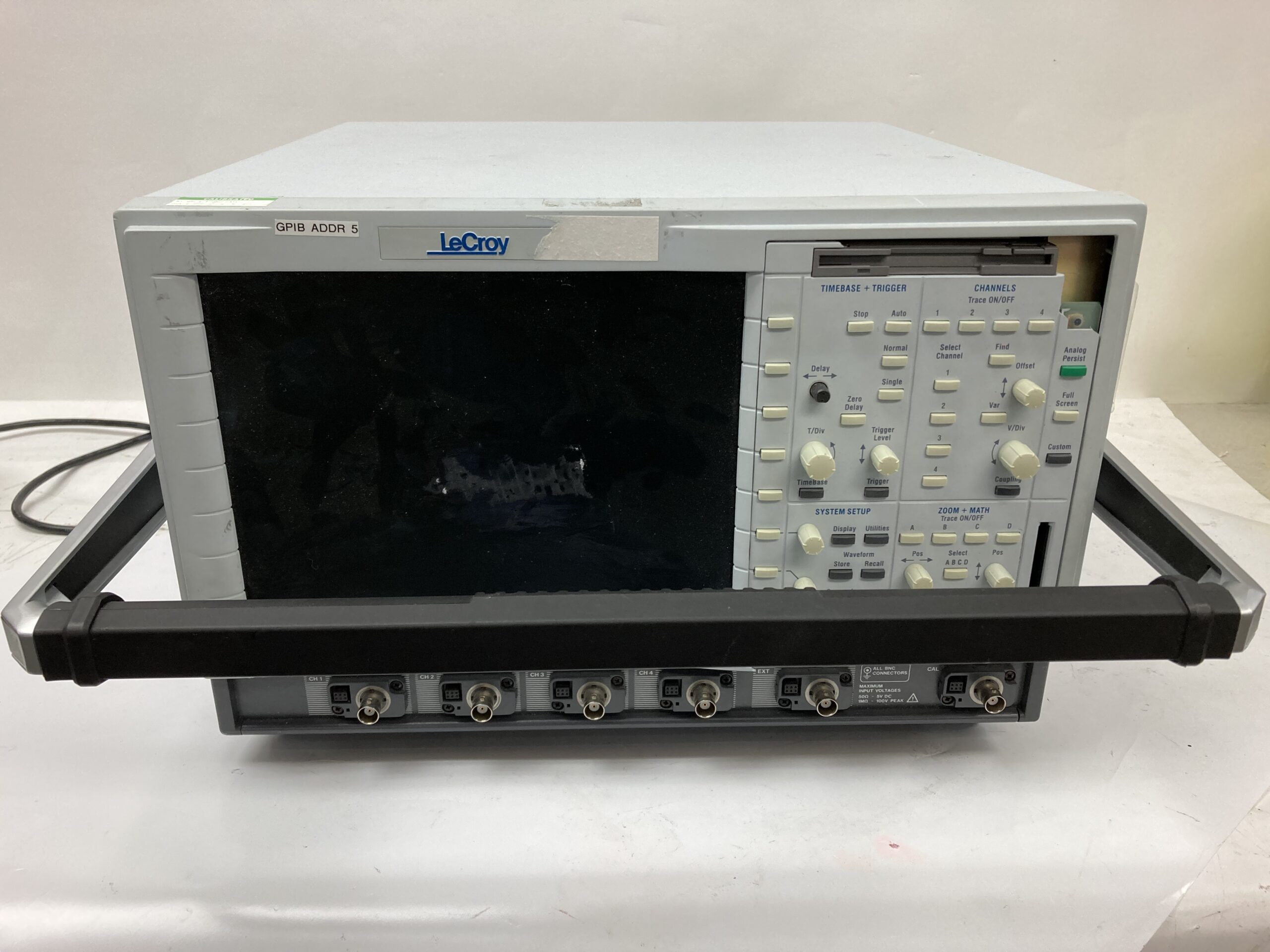
LeCroy LC684DM Oscilloscope (parts only)
224098875,00 ₽LeCroy LC684DM Oscilloscope (parts only) Needs Repair, Parts Only Check BMI Stock for More Items ***72120***
-
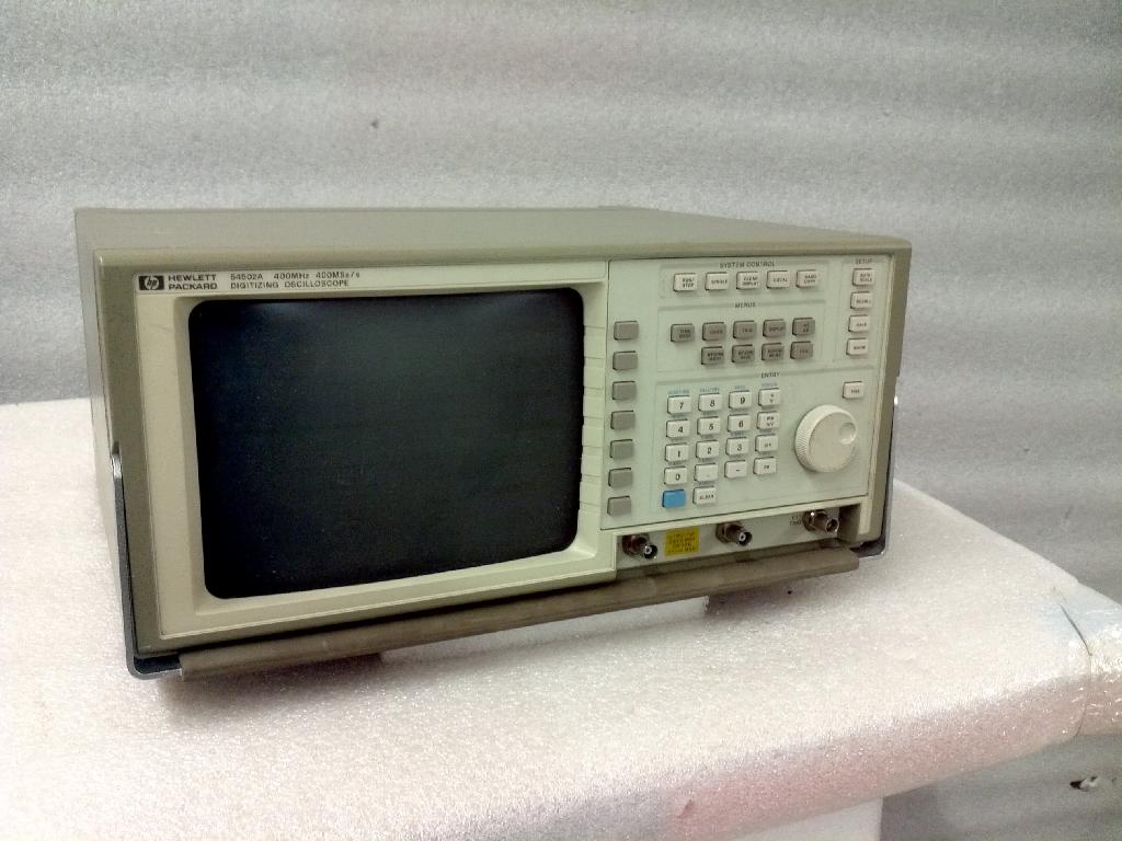
HP 54502A Digitizing Oscilloscope 400MHz 400MSa/s
22500,00 ₽This HP 54502A Digitizing Oscilloscope has been tested and is not working properly – selling as parts.