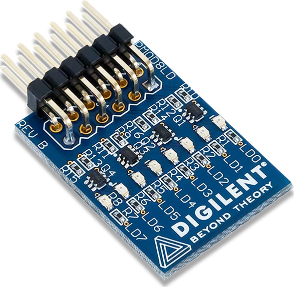
Digilent Pmod8LD – Eight High-Brightness LEDs
21.01.2025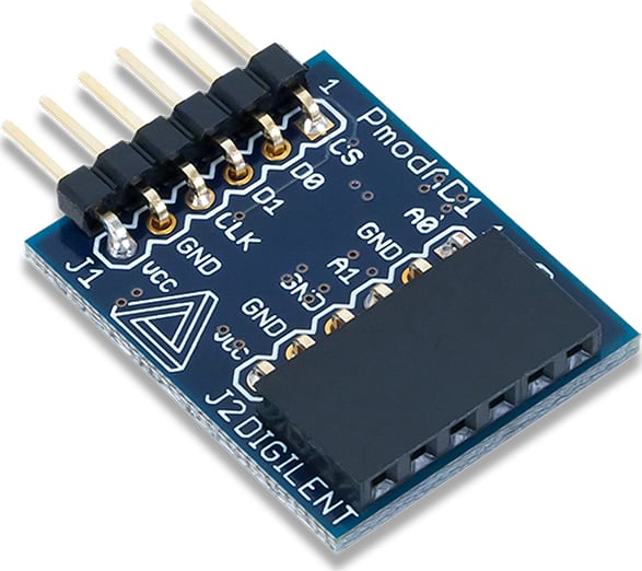
Digilent PmodAD1 – два 12-битных АЦП входа
21.01.2025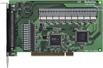
Autonics PMC-4B-PCI Motion Controller
Motion Controller, 4-Axis Programmable, Connection Type
394650,00 ₽
Description .da-AutonicsBlueBg { background-color: #fe5e01, } .da-AutonicsDarkBlueBg { background-color: #525050, } .da-ilf-gsep h3{ color: #ffffff!important, } .da-sep h3{ color: #ffffff!important, } .da-popup-img { margin: 70px auto, padding: 20px, background: #fff, border-radius: 5px, width: 50%, position: relative, transition: all 0.5s ease-in-out, max-width: 800px, } .da-popup-img h2 { margin-top: 0, color: #333, font-size:16px, } .da-popup-img .da-close { position: absolute, top: 0px, right: 10px, transition: none, font-size: 30px, font-weight: bold, text-decoration: none, color: #333, } .da-popup-img .da-close:hover { color: #888888, } .da-popup-img .da-content { max-height: 30%, overflow: auto, } .da-sm-img{ box-shadow: 1px 2px 3px #eeeeee, border-radius: 5px, } .da-sm-img:hover{ box-shadow: 1px 1px 2px 1px #aaa, transition: all 0.5s ease-in-out, } .da-img { max-width: 100%, height: auto, margin: auto, } .da-overlay { position: fixed, top: 0, bottom: 0, left: 0, right: 0, background: rgba(0, 0, 0, 0.7), transition: opacity 50ms, visibility: hidden, opacity: 0, z-index: 1000, } .da-overlay:target { visibility: visible, opacity: 1, } .da-ilf-grey{ background-color: #E3E3E3,} .da-ilf-blue{ background-color: #e7f2f8,} .da-row{width:101.3%,padding:10px,clear:both,float:left,margin:10px auto, margin-left:-.3em,} .da-table-striped { border-collapse: collapse, width: 100%,} .da-table-striped tr:nth-child(odd) {background-color: #f2f2f2,} .da-table-striped td { padding: 8px, font-size:16px,} .da-table-striped th { padding: 8px, font-size:16px, background-color: #565952,} Autonics PMC-4B-PCI 4-Axis Board Type Programmable
Motion Controller
- 2/3-Axis constant linear velocity
- Compatible with windows 98, NT, 2000, XP, 7
- PC-PCI card
- Auto home search and synchronous operation
- Interpolation on circular/linear, bit pattern/continuous/ ac/ deceleration drive
Ordering Information System Dimensions Connections Connection of pulse output signal for operating driver(nP+P/N, nP-P/N)
PMC-4B-PCI outputs pulse for operating driver as +/- of CW/CCW output using Line driver (AM26c31) and refer to the follows connections of motor driver with photocoupler and line driver input.
- Connection to motor driver with photocoupler
- Connection to motor driver with photocoupler
*It is recommended to use twisted pair shield wire for pulse output signal of driver operation regarding EMC.
Connection of common output signal (nOUT4 to 7)
Output signal is outputted by buffer(74LS06), and all outputs are OFF after reset.
Connection of encoder input signal(nECAP/N, nECBP/N) and nlNO+/- signal
- Connection of encoder input signal and auto output line driver
*Encoder A, B, Z phase are same connection.
Example for the connection of encoder input signal and NPN open collector output encode
*Encoder A, B, Z phase are same connection.
Connection of input signal (nIN1 to 3, nINPOS, nALRAM, nEXP+/-, EMG)
Connection of limit input signal(nLMIT+/-)
The outgoing cable of limit signal can be affected by noise, it can not be removed only with photocoupler, so, the filter circuit is built in and set enough passing time. (FL=2, 3)
Похожие товары
-
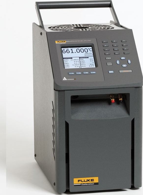
Fluke 9173-E-R-156 Metrology Well with 9173-INSE and Built-In Reference
3348450,00 ₽METROLOGY WELL, 700C, W/9173-INSE, W/REF, 115V
-
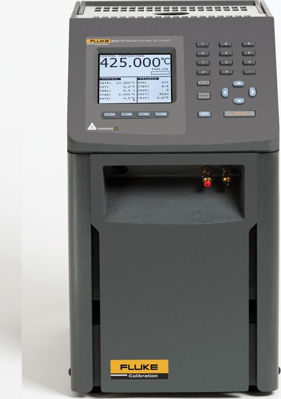
Метрологический калибратор Fluke 9172-E-156 с 9172-INSE
2316150,00 ₽МЕТРОЛОГИЧЕСКИЙ КОЛОДЕЦ, 425C, С 9172-INSE, 115 В
-
Метрологический калибратор Fluke 9173-C-156 с 9173-INSC
2894400,00 ₽МЕТРОЛОГИЧЕСКАЯ КОЛОДЕЦ, 700C, С 9173-INSC, 115 В